
Latest update for my project to provide an open source design for a BusKill cable.
Status
In my last update, I shared the instructional video I created that will be part 1/2 videos that show the decoupler’s assembly.
The decoupler created while filming the instructional video had a connection that was too weak. I wasn’t sure if it was because of the magnetic strength of the disc magnets used or if it was something I could fix with a better design of the 3D printed “faces”.

With funding from the BusKill Open Collective, I was able to purchase 16 n42 cube magnets and 16 pogo pins, enough to make 4 prototypes. I also purchased for myself additional N42 and N52 cube magnets for personal experimentation. I was 90% that the N42 magnet strength is sufficient, but I wanted to check the difference between the strengths for myself. I had read that N42s are very strong and useful for most applications and that N52 are double the price for only 20% more power.

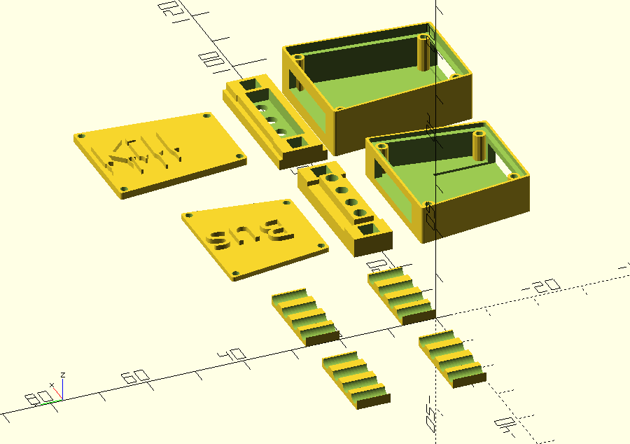
I printed version 3.9.0 of tprinted version 3.9.0 of the case (OpenSCAD file, STL file)printed
I began working on 2 prototypes:
- Gold – To test N52 Magnets (get it? gold magnets gold prototype?)
- Silver – To test N42 Magnets and create a demo video
However, while my initial intention was to test the magnet strengths, it didn’t quite turn out that way. I ended up with two prototypes that helped me with a couple other design problems – USB port/connector orientation and pogo pin/receptor positioning.

Gold
I assembled the gold prototype swiftly. During this process, I realized I hadn’t developed a proper rule of thumb for the orientation of the USB male and USB female in relation to each other. I thought that it had been that both were “upside down” in relation of the conductive prongs. But this is incorrect.
The way I advise orienting them is as follows: (1) USB male, especially if it does not have prong connections, should be added to the part with the soldering joints facing up (2) USB females usually have prong connections. The USB male and female should not be able to connect. so insert the USB male into the male to double check, and whatever orientation the USB female is in, it should be the opposite during assembly.
Since I didn’t know this going in, I did end up putting the magnets into this prototype so that they would connect the opposite orientation as correct. I had partially assembled the Silver prototype, but hadn’t added the magnets yet. So I set them up so that the Gold prototype to connect with the Silver prototype.
This created one functional prototype, but neither actually using solely the gold magnets.

Silver
So as mentioned, I had started working on the Silver prototype at the same time as the Gold prototype. I took this opportunity to also test pogo pin positioning. If you look closely at the pogo pins, There is a teeny ridge on them. This ridge is slightly below the edge, a hard surface that the pogo spring collapses into so when the pin is compressed.

With my current the design, the ridge often catches on the top of the hole. However, 3D prints are rarely perfect, there’s usually some issue with at least one of the holes. Nevertheless, it seems beneficial to potentially use this ridge to make assembling easier. But to use this, the part needs to be designed accordingly.
The gold prototype lined up the pogo pins at the edge, the silver prototype lined up the pogo pins at the ridge.


It did appear that the silver prototype has a harder time making the connection. This indicates to me that if I want the pins to line up on the ridge instead of the edge, I should potentially increase the distance of the pogo receptors from the surface.

What’s next
I want to make some corrections to the 3D model before proceeding and creating a version that I’ll use to create written documentation.
- Increase the thickness of the outer walls of the enclosure bodies. Thin is good, but too thin means it’s easy to break during assembly. (If you look closely at IMG 5, you can see that the wall of that prototype has been dented)
- Adjust the placement of the wire channels in the jig pieces – sometimes they’re hard to close over the wires.
- Adjust the distance of the pogo receptors and the pogo pin during connection.
I’m making these changes to version 3.1.
For more information
- Original rationale: BusKill hardware wishlist
- Progress updates, the latest versions of the OpenScad and STL files, and BOM are available at the GitHub repo.
