
Background
On July 3, 2023, I successfully created a prototype of the magnetic release. For those just tuning in, this is a project that aims to create a 3D-printable magnetic decoupler that allows for easy ejection of a USB-A extension cord from the USB-A port. This decoupler is used with a PC that has BusKill software installed. BusKill software automatically locks the screen when it detects a USB ejection event. The cord is attached to a USB attached to a person, and so if the person is separated from the computer, they’re immediately logged out and their data is safe.
In May-June, I printed 35 iterations of the case and experimented with different parts, processes, and techniques. Each component of the case brings its own design challenges – the magnets, the pins, the receptors, the wires, the cable, and the case itself.
For previous logs, please see posts in the BusKill category.
For information on technical terminology used in this post, see the glossary.
Description
The prototype is a proof of concept. It’s the minimum viable assembly of parts that successfully complete the objective of a functional decoupler. It includes two printable parts, the Breakaway and the Release that will be the “faces” or “contact points” of the final printable parts.
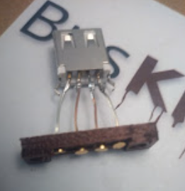
The Breakaway is an assembly of a Breakaway printed part, 22 awg wire, pogo receptors, USB port (female), and disc magnets.
The Release is an assembly of a Release printed part, 22 awg wire, pogo pins, USB male, jig, and disc magnets.
Procedure
Tools
Buy soldering iron (paid link)
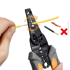
Buy wire stripper (paid link)
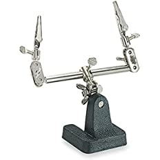
Buy helping hands (paid link)
Note: I use these to prevent burning my fingers, but they’re usually used for prototyping. Tweezers would work too.
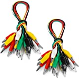
Buy hand-held alligator clamps (paid link)
Materials
For more info, see BOM.
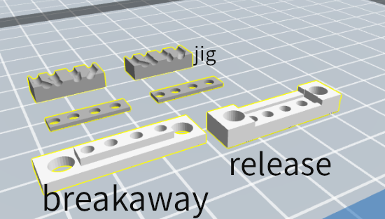
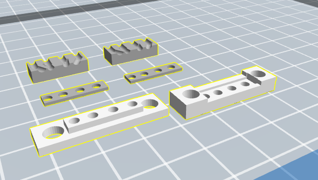
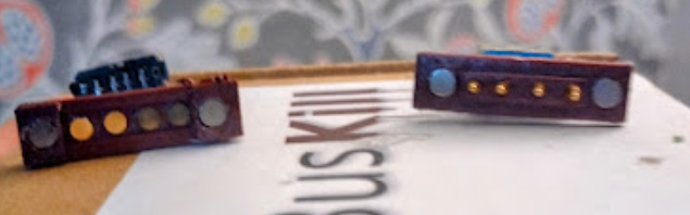
The “breakaway” consists of areas for two disc magnets and an indention to house pogo receptors.
The “release” consists of areas for two disk magnets and an extrusion to house pogo pins.
The “jig” are parts that houses wires and keeps them from moving.
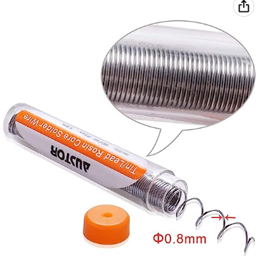
Buy rosin core solder (paid link)
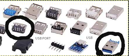
Buy usb assortment (paid link)
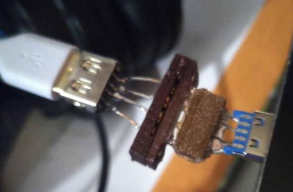
Note: At this stage of the prototype, you’re really fine using any usb port or USB that you can salvage or purchase. You can salvage a port from a charger, or a USB from a cord.
However, there are a couple of things to keep in mind if you can:
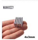
1) Shorter, more compact USB port designs are great, such as the one circled above. The lighter the weight and the shorter the length of the USB port side of the decoupler, the stronger and more secure the magnetic connection, reducing risk of unintentional disconnection.
2) Some USBs are easier to solder to than others. I look for nice flat contact area or prongs for soldering to.
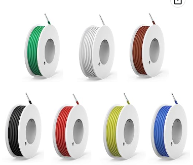
Buy 22awg solid wire (paid link)
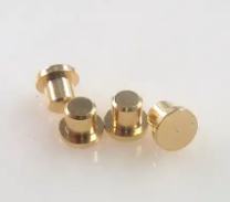
Circular SMD Contact Pad
3.0 mm Diameter Flange Height
2.0 mm Flat surface Gold plate
Buy pogo receptor (alibaba)
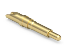
Max working height – 8.72mm
Recommended working height – 7.58mm
Min working height – 6.43mm
Circular – 1.98mm
Plunger size- 1.07mm dia
Buy pogo pin (digikey)
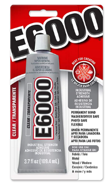
Personally I use E6000.
Buy E6000 glue (paid link)
Important! USB 3.0 is too complicated, stick with 2.0
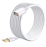
Buy USB 2.0 Extender Cord (paid link)
NOTICE: THIS PROTOTYPE IS VERY FRAGILE AND NOT SUITABLE FOR USE AS AN ACTUAL BUSKILL DECOUPLER. THIS PROCEDURE IS PROVIDED FOR EDUCATIONAL PURPOSES ONLY.
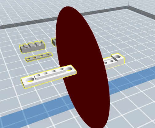
- Add dengineering v.2.3.8 STL to your slicer program
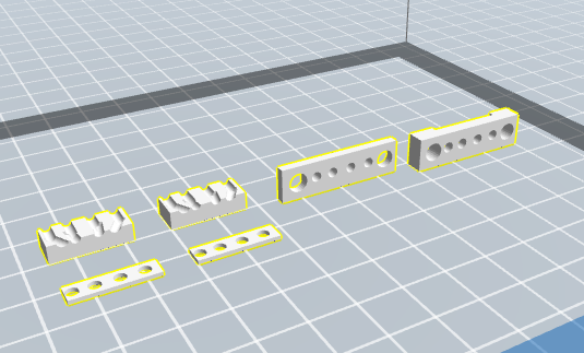
- Edit the file to cut the “faces” from the rest of the parts and from each other.

- Rotate them +90 degrees on the x axis and make sure both are moved to the surface.

- Print with .2mm layer height and on a “raft” for best results.
- Start work on the Breakaway. The Breakaway is an assembly of a Breakaway printed part, 22 awg wire, pogo receptors, USB port (female), and magnets.
- Solder four wires to a USB port. Leave enough room to work with, because you’ll clip the wire.
- Slide the Breakaway printed part on to the wire pushing down so that the wires spread and curve into the part. As you push there will be resistance, and you want to stop when you have the right amount of resistance. Clip the wires at this point so that all of them are level when the part is pushed in.
- Keep the part in (although it will move probably) while you solder the pogo recs to the end of the wire. You’re soldering the small end to the wire. It’s tricky to keep the recs in the proper orientation, but understand that they’ll need to be flat against the surface of the print. Note: I use alligator clips and helping hands quite a lot, sometimes two helping hands and alligator clips in my hand, the parts are small and they get hot. Be aware that plastic components will melt or warp as the heat travels up the wire, so work quickly.
- Then when you’re done you push the part up to the pogo receptors. Finagle as you need to to make it so the pogo recs are where they need to be.

- If you’re satisfied, glue in place.
- Start work on the Release. The Release is an assembly of a Release printed part, 22 awg wire, pogo pins, USB male, jig, and magnets.
- Insert four wires into four pogo pins. Make sure you have enough to work with, you’ll be clipping them.
- Get your jig and line up the pogo pins at the edge and glue them there.
- Once the glue is dry, solder the wires to the usb. Note: when soldering, be aware that plastic components will melt or warp as the heat travels up the wire, so work quickly.
- Add the plastic housing. When satisfied, glue in place.
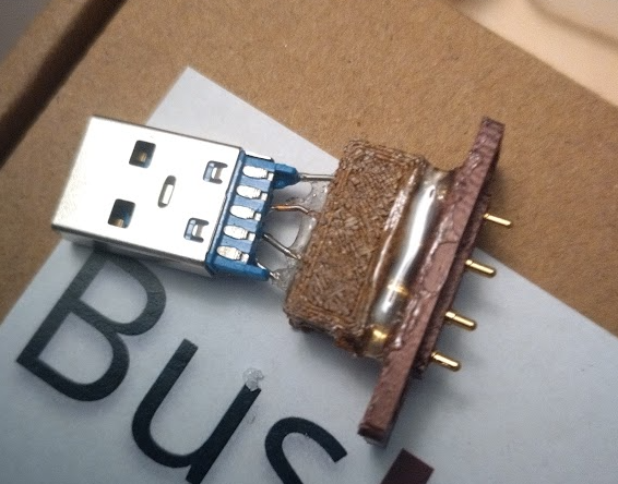
- Glue in the magnets on both sides.

- For Linux, run the dmsg -w in a terminal window. This way, if there are any problems, you may receive information about what went wrong.
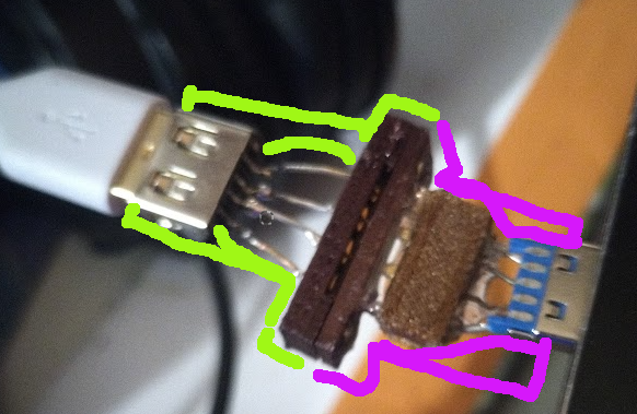
- Assemble your cable:
- Insert your USB storage drive into the USB Extender Cord’s USB Port.
- Insert USB Extender Cord’s USB male into the Release of your decoupler.
- Insert Breakaway of the decoupler into the computer’s USB port.


Next steps
For this to be suitable for its purpose, there are at least three more necessary changes.
Firstly, the design of the faces needs additional elements that will make them more securely attached.
Secondly, the design of the face also needs to accommodate slightly larger/stronger magnets. It is currently very easy for the cord to detach itself when not intending to.
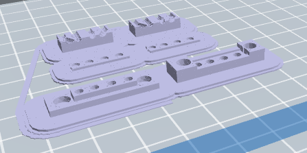
Finally, of course, the body of the case needs to be designed. In the image below, I have provided a rough outline of how I think the case will be designed.
Acknowledgements
I want to give my deepest thanks to those who support BusKill on OpenCollective, who made it possible for me to purchase the materials necessary for this work.
In the Press
Hill, Ash (May 02, 2023). “3D Print Your Own USB BusKill Module to Protect Data“. Tom’s Hardware.
