

I’ve been working on an open source hardware project for a couple of years called BusKill. It’s a security cord that shuts down a computer if it’s physically separated from you.
Quick overview
My colleague Michael Altfield and some volunteer developers wrote BusKill software. This software is free and open source and works on Windows, Mac, and Linux. The software is security-focused and allows you to verify the signatures before installing the files.
Once you install and run BusKill, you can use the sleek, minimalist GUI to arm and disarm it. When you arm BusKill, it will take a security action when the computer if it detects the USB has been removed. The default action is to lock the computer, but it is possible to configure options such as erasing data or shutting the computer down completely. If you disarm it, there is no action if the USB is removed.
The software is meant to run while the user has a BusKill security cord. You can purchase the security cord or you can make your own. On one end of the security cord, you have a USB that attaches to your person. You can pick the smallest, cheapest USB available, because you do not need to store any files on the USB for BusKill to work. The important thing is that the USB has a hole so that you can attach a carabiner. Most people attach the carabiner to their belt loop.

The USB is inserted into the female end of a USB female-to-male cord. This is not too unlike a typical USB extender cord. However, this cord should have a magnetic breakaway near the USB side of the cord. This allows the connection to break if someone attempts to put distance between you and your laptop.
Why?
We think there are multiple communities that need something like this, but the driving force behind what we do is to provide a tool that protects activists and journalists. However, anyone that uses their computer in public, such as in coffee shops and the like, and logs into data that an adversary might want to access by force, could benefit from having BusKill.
Developing the Prototype
Ideation
3 years ago, Michael asked me if I was interested in developing a 3D-printed case for the magnetic breakaway. He told me he wanted the following features:
- The case should be as small as possible, because shouldn’t block neighboring ports or sit heavy in the port causing it to bump into objects on the desk.
- The case should be able to be dissembled, so that people can make sure it isn’t tampered with. It shouldn’t be glued together.
- In order to avoid using glue, we had a factory specially manufacture some hexagonal shaped magnets that we believed would be able to sit inside the printed part without glue.
- Much like USB breakways that are designed to prevent wear and tear on ports, the case would house pogo pins and magnets, and a USB.

The funny thing is, things changed a lot over the years.
- We learned that we didn’t have to put the magnetic release near the port, but that it is better to put it near the person.
- We realized that these parts are so small, the magnets so strong, that it really couldn’t be completely assembled without glue. The outer case, sure, but magnets, pogo pins, pogo receptors and the like must be glued.
- Because we are now ok with having to use glue, it is probably better to use easy to find disc magnets.
- The case doesn’t actually need to house the USB at all, but it does need to house the pogo pins and magnets.
This process taught me about the realities of going from idea to execution.

My Journey with OpenSCAD
When I started this project, I was novice-beginner level with OpenSCAD. I had designed something of similar complexity about 8 years ago. It was a model of an assembly related to creating a timelapse camera for Raspberry PI. I recall the person I created that file for ended up refactoring all my code to be more parametric. I soon learned that I had a lot to learn about actually writing good, parametric OpenSCAD code….

I knew that I would write modules, and I knew about the primitive shapes, and about difference functions, and such. However, I didn’t quite realize that if I was writing a module that would be shared it would need to not be nested inside another module. I didn’t know that I should group all the shapes I was going to difference in one module and all the shapes that made the shell in another module. I rotated things before transforming them sometimes, and other silly things. My code was bad! Even though I commented my code thoroughly, it was a mess! It was hard to use myself, let alone sharing with the open source community!
I had to rewrite it all… it taught me that sometimes you have to break things to fix them, you have to go backwards to go forwards.

Prototype Begins
And so, chipping away whenever I could whether it was few minutes or a few hours… over time… I am now working on the PROOF OF CONCEPT / 1st Prototype.
And that’s what I’m here to share with you today. However, guess what – it’s still not done. Sad story! You’ll see in the updates below.
Tools Used:
Wire stripper, soldering iron with fine tip, helping hands, xacto knife, painters tape, multimeter, alligator clips
Materials Used:
3D printed case (6 pieces), 8 magnets, 4 pogo pins, 4 pogo receptors, solder, wire, usb-to-usb-port cord, usb, carabiner, E360 glue
CAUTION: many materials used are hazardous, please follow the safety labels if you do this at home. Proper ventilation, skin, eye, and lung protection when required.
Note: If you can’t acquire a usb-to-usb-port cord, it’s possible to make your own as long as you have a spare usb-to-usb cord and a spare charger that you don’t mind dissembling for this purpose. However, it’s important to make sure that the cord is a data cord, and not a charging cord only. You’ll know because data cords have 4 wires whereas charging-only cords have two wires.
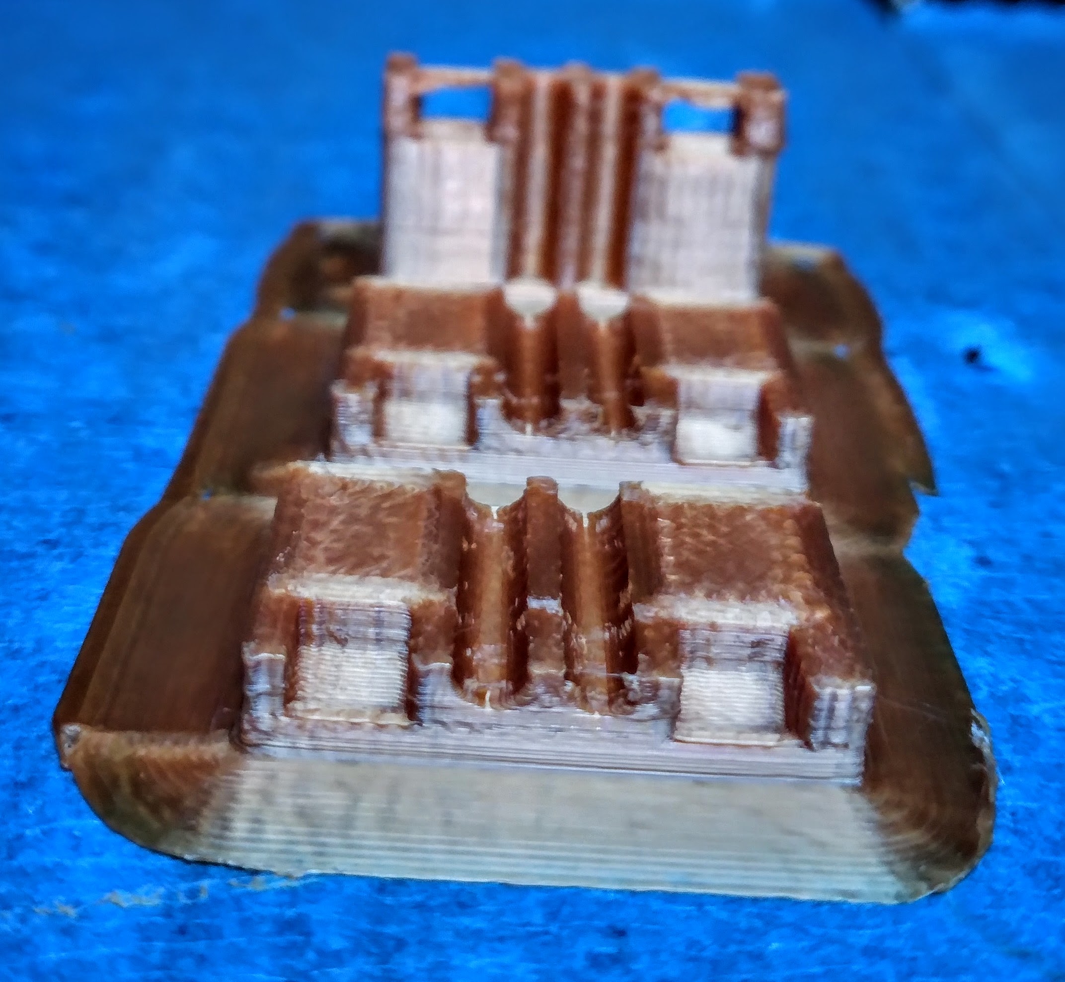
Print the Case
- This prototype uses magnetic_release_B_v0.9.stl. Download from the Github Repository: https://github.com/BusKill/usb-a-magnetic-breakaway
- I have a Flashforge Creator Pro and use the Flashforge slicer. I print Hyper Quality and using a raft. Takes about 45 minutes.
Assemble the cable
Step 1:
Cut near the port near where the USB attaches to the cord. Splice the wires.

Step 2
Glue magnets to the middle piece:
- Arrange magnets in place (Optional: mark the tops and bottoms of the magnet with perm marker)
- Apply glue to the middle piece
- Slide in the middle piece for one side.
- Slide in the middle piece for the other side.
- Use a thin but firm material to carefully separate the pieces and allow glue to set.
Tip: I put down a little blue painter’s tape on my workspace where I want to put my pieces down to dry. Also, there’s very little room for plastic-out-of-place and 3D printers don’t always print perfectly. If your magnets aren’t sitting securely, there may be a bit of plastic blocking the way that you need to trim out.
Step 3
- Solder USB wires to pogo pins
- Solder USB wires to pogo receptors
Note: There is a slight asymmetry in the design, you’ll notice a thicker side and a thinner side. This can help you identify the “top” and “bottom” pieces are oriented correctly.
Tip: Personally, I find the original USB wires so tiny and unwieldy that it’s kinda hard to solder them to the even pogos… so I spliced them into breadboard wire first.

Step 4
- Consult pinout diagram to arrange wires correctly.
- Use marker to label wire channels in the printed piece.

Step 5
Glue wires carefully to the top and bottom parts of the case.
The spring part of the pogo pins when pressed should be flushed with the edge of the case, but when not pressed should poke out.
https://photos.app.goo.gl/JJzUuC3258sSGcfv7
Step 6
When the glue is dry, sandwich the middle piece between the top and bottom pieces and wrap securely with electrical tape.
NOTE: In the image below the wires are not actually glued yet. I was just sort of mocking it up.

Where I’m at Now
Before I glued the wires in, I wanted to make sure everything was working and wired correctly.
So I dissembled and attached each wire to itself with alligator clips to test whether my computer would detect it. It failed.

It seemed to me that if this didn’t work then if I proceeded onward it was likely not going to work. I’m a little perplexed. I tried continuity testing and I’m not sure if my Multimeter sucks or something. At first, I thought I was getting sensible advice from it, but it turned out that it really didn’t seem that way.
So I started over with the splicing… which really hurt because I did think that I had soldered everything really well! And even without any wires spliced in… the wire connected to itself with the alligator clips still isn’t functional. So what is the problem here? I can’t proceed until I figure it out. I’m asking around to anyone with some experience to try and get advice.

1 Comment